Cessna 172 Instrument Panel: Full Cockpit Layout Guide
Dec 15, 2025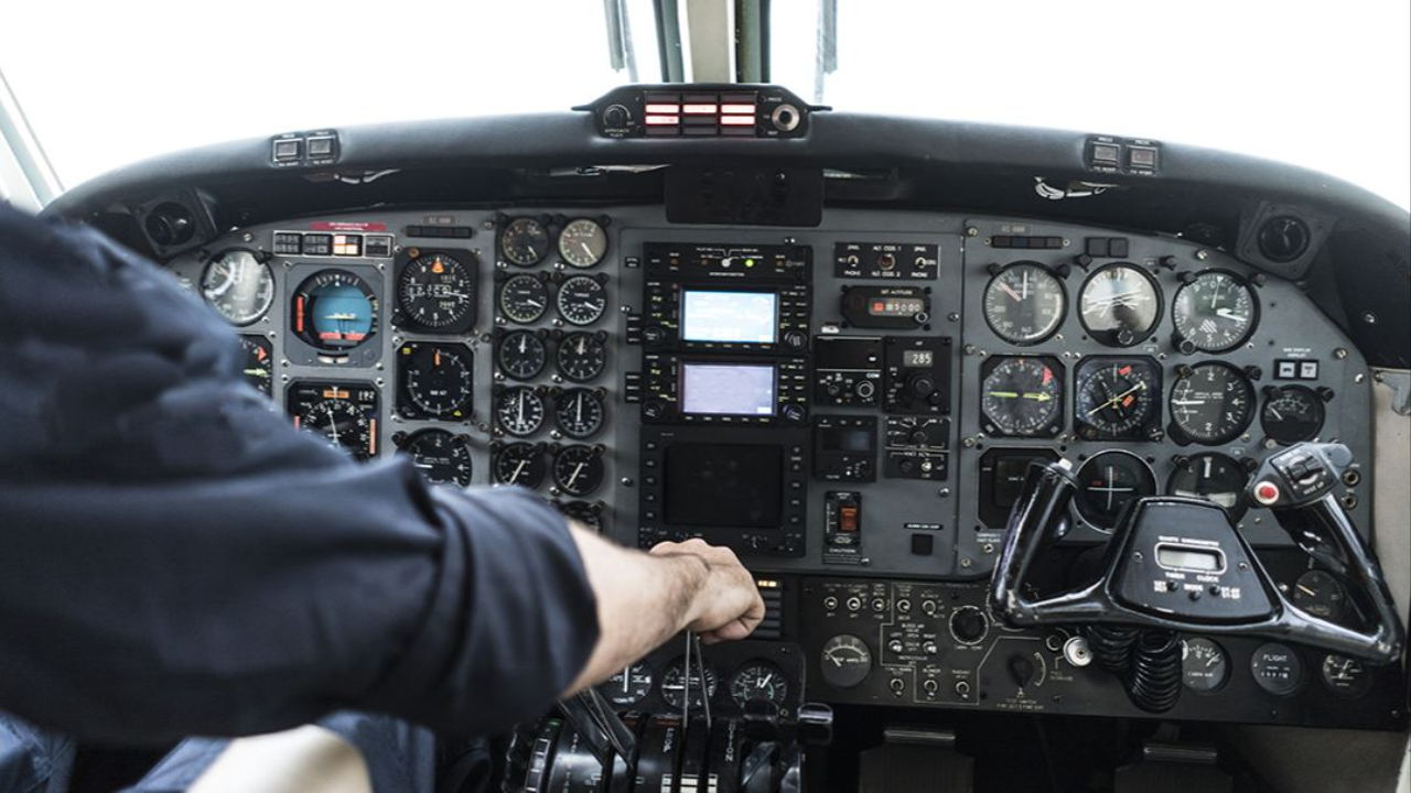
Discovering the Essential Guide to the Cessna 172 Instrument Panel the beating heart of the world’s most popular training airplane, including the widely used Cessna 172R cockpit that many student pilots first learn in.
Whether you're a student pilot or a seasoned aviator, mastering this cockpit layout is pretty much key to flying safely and with confidence. Let's dive in and explore every single control, instrument, and feature that's made the Cessna 172 a pilot’s favorite.
Cessna 172 Instrument Panel Overview
Thoughtful Design for Pilot Efficiency
The Cessna 172 instrument panel is a prime example of decades of refinement aimed at one goal making flying safer and more efficient.
The layout is thought through , with the most important flight instruments right in front of you, and secondary systems grouped around the cockpit in a way that makes sense. That means you can focus on the essentials of flying, rather than being distracted by a cluttered mess of controls.
The Iconic Six-Pack Arrangement
Centerpiece of the center panel is the traditional "six-pack" arrangement of the primary flight instruments all lined up in a standardized T-configuration.
These instruments give you the lowdown on your attitude, altitude, airspeed and direction vital information that you need to keep track of. The way it's laid out means that you don't have to take your eyes too far to scan all the key data - which is especially useful during those high-workload moments in the air.
Organized for Seamless Workflow
The engine monitoring gauges are placed on the right side of the panel so you can keep an eye on the engine health without taking your attention away from the instruments.
The electrical switches and circuit breakers are positioned either behind the control yoke or along the left-hand edge easily accessible but not in the way. The avionics, radios and navigation gear are all on the middle of the panel, so you can get to them easily when you need to make a call or navigate somewhere.
Modern Features and Ergonomic Design
Many modern Cessna 172 models now come with the latest in digital cockpits like the Garmin G1000 which combines the best of the old with the latest in digital tech.
These systems add in features like synthetic vision and weather information, so you can get a clearer picture of what's out there. The layout is designed for single-pilot operation, so you can get everything you need within easy reach making for safer and more comfortable flying even on longer trips.
Learn more in Flight Nerd Air Force: Aviation Training

The Classic Six-Pack Flight Instruments
The standard T-shaped arrangement used in most training aircraft since the 1940s places the six most critical flight instruments in two rows directly in front of the pilot. This configuration has become so universal that transitioning between different aircraft types requires minimal adjustment for instrument-rated pilots.
Two rows of three instruments each provide essential flight information in a logical, easy-to-scan pattern. The top row contains instruments that show where you are and how fast you’re going, while the bottom row indicates how you’re moving through space and in what direction.
Top row consists of the Airspeed Indicator, Attitude Indicator, and Altimeter – the three instruments that provide immediate situational awareness about your aircraft’s energy state and position. These instruments use different systems (pitot-static and vacuum) to ensure redundancy in case of system failures.
Bottom row includes the Turn Coordinator, Heading Indicator, and Vertical Speed Indicator, which show your aircraft’s movement trends and directional orientation. These instruments help you maintain coordinated flight and track your desired course accurately.
Vacuum-driven gyro system powers the attitude and heading indicators through an engine-driven pump that creates suction to spin internal gyroscopes. This mechanical system provides reliable operation independent of electrical power, though electric backups are often installed for redundancy.
Pitot-static system feeds the airspeed indicator, altimeter, and vertical speed indicator through pressure differentials measured at the pitot tube and static ports. Understanding this system is crucial because blockages can affect multiple instruments simultaneously.
Airspeed Indicator (ASI)
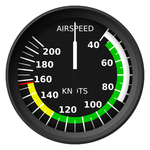
The Airspeed Indicator a key player in the six-pack instrument layout up top left is super important for pilots to keep tabs on their flight's energy levels at all times. It shows you your airspeed in knots, with some very handy color coded arcs that help you navigate the different flight modes and limitations.
The white arc is the magic number for flap deployment you've got to stay in that zone when landing or approaching to avoid any issues. The green arc is where the majority of your flying will happen that's where you'll find the normal operating speeds for standard flight.
Above the green arc you've got your yellow warning zone and that's only for smooth air, folks, because if you're flying in the yellow you don't want to be putting any extra stress on the aircraft.
And then there's the red line that's the never exceed speed (VNE), and let me tell you, you don't want to cross that line unless you want to risk causing damage or a bit more. The ASI works by using the pitot tube to measure the dynamic pressure, and if you can't tell the difference between indicated and true airspeed at higher altitudes then you're in for a world of trouble.
Attitude Indicator
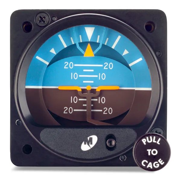
The attitude indicator is one of those super important instruments that keeps your aircraft flying straight and true - especially when you're flying the gauges and can't see a thing outside. It gives you a pretty clear picture of what's going on, with a pretend horizon up top that's a nice shade of blue and a brown landscape below, just like the real thing.
And of course there's a tiny aircraft symbol that moves around to show you just how much pitch and bank you've got going on with the pitch marked off in nice big 5-degree chunks, and bank angles at 10, 20, 30, 60 and 90 degrees, all to make those climbs, descents and turns a whole lot easier.
Now the attitude indicator itself is powered by either one of those old vacuum driven gyros, or newer electric systems and either way, it gives you that all important accuracy and reliability.
Vacuum systems work by spinning a mass around in a circle to keep it steady, so you don't lose your orientation even when the power goes out. And on the other hand, electric indicators come with extra features like slip and skid indicators, and even a display of how fast you're turning - which makes life a whole lot easier, and requires a lot less maintenance, when you're flying by the gauges.
Altimeter
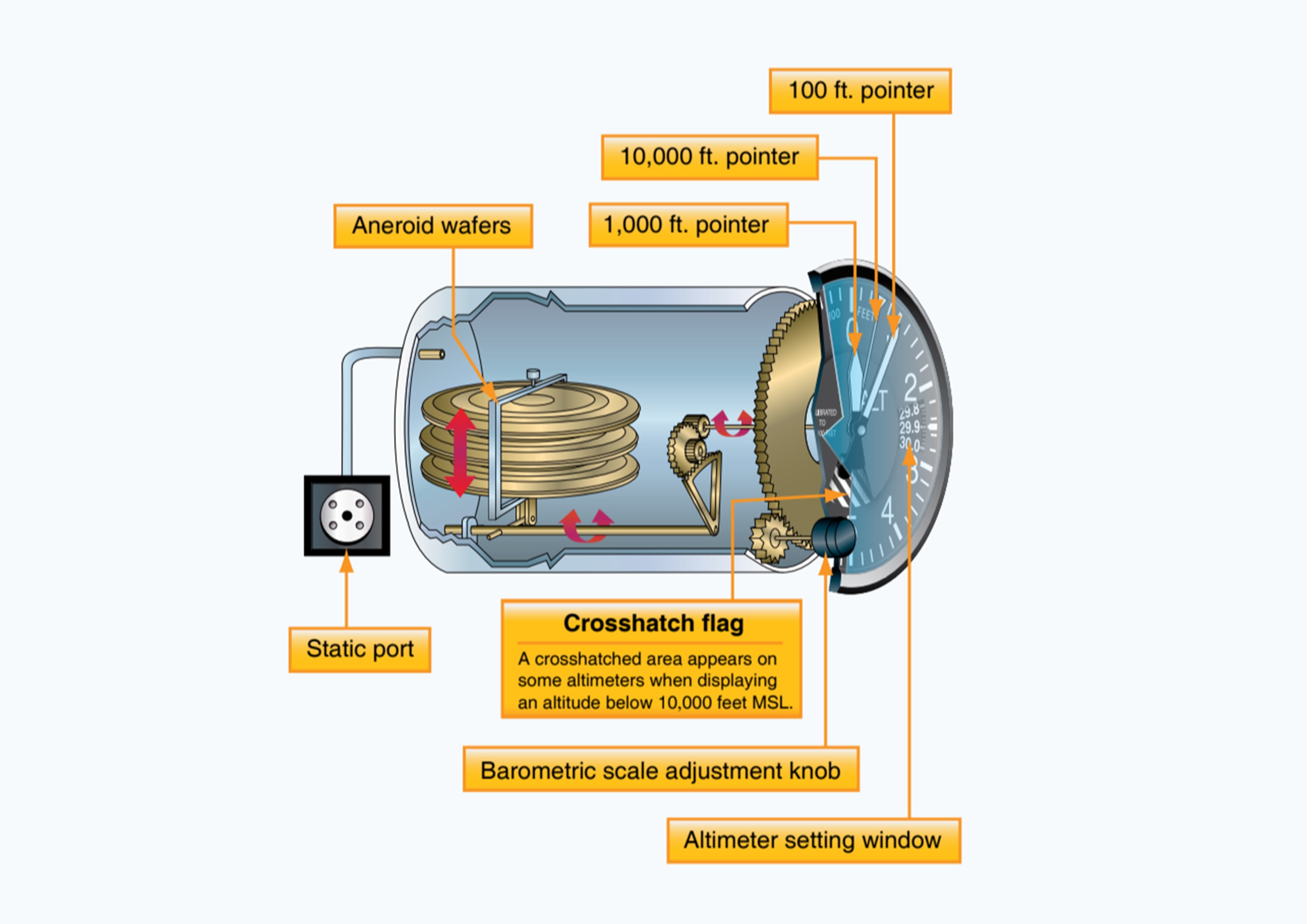
The altimeter is a crucial cockpit instrument that shows pressure altitude above sea level using a three-pointer system. Each pointer represents different altitude increments 10,000 feet, 1,000 feet, and 100 feet to provide precise altitude readings. Pilots must interpret all three pointers carefully, especially for critical functions like ensuring terrain clearance, maintaining traffic separation, and adhering to altitude regulations.
The Kollsman window allows pilots to adjust the altimeter's settings to reflect local barometric pressure, ensuring accurate readings both on the ground and in the air.
Altimeter readings depend on the static pressure system, using aneroid wafers that respond to changes in atmospheric pressure. Accurate settings are vital as blocked static ports or incorrect barometric adjustments can lead to significant altitude errors.
Features like the cross-hatched area below 10,000 feet serve as reminders for regulatory requirements, such as oxygen use and transponder operation. Backup static sources add a layer of safety to prevent errors during instrument flight.
Turn Coordinator
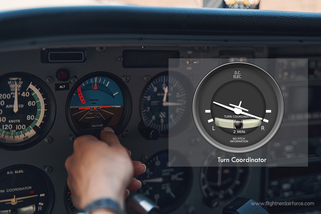
The turn coordinator is a critical flight instrument that combines rate of turn and slip/skid information to ensure coordinated flight, especially in instrument conditions where outside visual cues are limited. The miniature airplane on the instrument displays the rate of turn in degrees per minute, with standard rate turns occurring at 3 degrees per second or 180 degrees per minute.
This standardization supports precise timing during instrument procedures. The instrument also measures roll and yaw rates, providing real-time feedback on turning performance.
A simple inclinometer, featuring a ball in a curved glass tube, shows whether a turn is coordinated. A centered ball represents proper rudder use, while deflection indicates slipping or skidding, which wastes energy and reduces passenger comfort.
Pilots can correct this by “stepping on the ball” to apply proper rudder input. Powered by an electric gyroscope, the turn coordinator provides redundancy, remaining operational even if the vacuum system fails, ensuring crucial turn and coordination information is always available.
Heading Indicator (Directional Gyro)
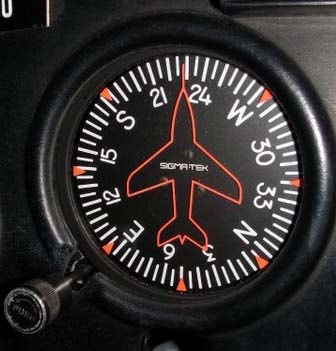
The heading indicator - or directional gyro - is a vital piece of navigation kit that gives you a rock-solid magnetic heading reference. Unlike a magnetic compass, which can go haywire when you're flying through turbulence and making sharp turns, the heading indicator stays steady even when things get bumpy.
It's got a fixed symbol for the aircraft, showing your current heading on a 360 degree compass rose, marked off in 5 degree increments. That makes it really easy to use the adjustment knob to set a heading "bug" - a clear visual aid for keeping on track with assigned headings or flight courses, especially when you're navigating by instruments or lining up for a landing.
Before you take off you need to manually sync the heading indicator with the magnetic compass, and that's not a one-off job - you'll have to do it again a few times during the flight to make sure it's still in sync, because time can affect the gyro's accuracy.
The heading indicator is powered by a vacuum-driven gyroscope, so it's immune to magnetic interference, which makes it a lot more reliable, even in tricky flying conditions. You should be checking it every 15 to 20 minutes - and having a good understanding of your particular instrument's drift rate is crucial if you want to stay on course and navigate accurately.
Vertical Speed Indicator (VSI)
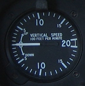
The VSI down at the bottom right of that six-pack cluster is a vital tool for pilots: it tells you how fast you're climbing or descending in hundreds of feet per minute and helps you keep your altitude steady and on-track. The scale is pretty standard: -2000 ft/min to +2000 ft/min, and it's got to give you the right lowdown on how to manage energy levels during different phases of flight.
When that needle's at the zero mark, you're flying level as can be. When it starts to move up, you're climbing. When it goes downwards, you're leveling off or even descending.
Now, things like how light the plane is, what the temperature is outside and how much grunt you've got from your engine can all influence what sort of climb or descent rate you're looking at. For example, a Cessna 172's pretty typical climb rates are somewhere between 300 ft/min and 700 ft/min.
The VSI works through a system that uses a calibrated leak to translate changes in air pressure into that climb or descent rate data, but be aware that you'll get a slight delay before you feel the effects of any big altitude changes.
Not because it doesn't work just because there's always a bit of lag when you're making quick adjustments.
Getting the hang of reading the VSI smoothly is key, especially when you're doing an approach or a steady descent & the rate is somewhere between 300 and 800 ft/min. You'll also want to be aware that blockages in the static system - or even issues with other instruments like the altimeter or airspeed indicator - could knock the VSI off-kilter.
Engine Instruments and Controls
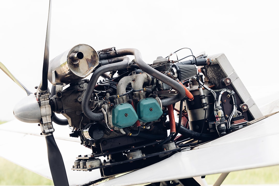
The engine monitoring system on the Cessna 172 provides a vital window into the health of the powerplant, as well as the overall performance of the aircraft.
These gauges give pilots the information they need to squeeze the best out of their engine, pick up on warning signs early, and fix any issues before they become major headaches.
By knowing what's normal and what's not, pilots can avoid costly repairs and keep the aircraft flying safely - which is basically the ultimate goal.
-
The tachometer is the one you'll want to keep an eye on most for engine RPM, it usually tops out at 2700 RPM for most C172s, but you should aim for something between 2200-2500 RPM for most flying. That's the sweet spot, but of course it all depends on where you are and how much performance you need. If you do go above that redline, however, you risk serious damage to the engine.
-
The oil pressure gauge is pretty important too, you want to keep it between 60-90 PSI for your Lycoming engine, that's the normal range. If it starts to drop off, you could have a serious problem on your hands like a pump failure or a leak in the oil system. Some models even have a warning light to let you know if things are getting bad.
-
The oil temperature gauge is your best bet for keeping your engine from overheating. It's a delicate balance between outside air temp and how hard you're pushing the engine, so keep an eye on it and see where it's at. If it starts to creep up and stay there, you may have a problem with your cooling system or you may just be asking too much of the engine.
Electrical System and Switches
The electrical system in a Cessna 172 powers critical equipment such as lights, radios, and avionics through either a 12-volt or 24-volt system, depending on the aircraft model. A clear understanding of this system, along with the functionality of various switches, is vital for effective power management and troubleshooting during flight.
Key Switch Functions
The master switch utilizes a split rocker design, controlling the battery (BAT position) and alternator (ALT position) independently. While the battery provides power to the electrical bus, the alternator generates output when the engine is running. Additionally, circuit breakers safeguard individual components, offering isolation during troubleshooting.
Lighting and Heating Controls
Lighting switches manage navigation lights, anti-collision beacons, strobes, and landing lights, which are essential for visibility and safety. Many pilots rely on strobe lights to enhance aircraft conspicuity during both day and night operations. Many aircraft also include taxi lights to improve ground visibility during low-light operations and assist pilots during ramp and taxi movements.
Landing lights, due to high current demands, should be used strategically. The pitot heat switch ensures the pitot tube remains ice-free, preventing airspeed errors in freezing or moist conditions.
Avionics and Fuel Systems
An avionics master switch powers navigation and communication systems while protecting equipment from start-up surges. Meanwhile, the fuel pump switch enables backup fuel delivery during mechanical pump failures or critical phases like takeoff and landing, ensuring uninterrupted engine fuel flow under all conditions an essential part of the fuel system Cessna 172 pilots rely on for safe and consistent operation.
Older panels may also include traditional navigation aids such as an automatic direction finder, providing bearing information to low-frequency ground stations for supplemental situational awareness, especially when integrating modern avionics devices into upgraded instrument panels.
Modern Glass Cockpit Options
The evolution of glass cockpit technology has revolutionized Cessna 172 and other aircraft, transitioning from traditional analog gauges to advanced digital displays.
These systems enhance situational awareness, improve operational efficiency, and prioritize pilot safety. Modern glass cockpits like the Garmin G1000 consolidate essential flight, navigation, and engine data into streamlined, user-friendly screens, offering invaluable tools for pilots especially when upgrading components sourced from suppliers known for fast shipping and consistently providing great service.
Primary and Multi-Function Displays
The Garmin G1000 features two major components: the Primary Flight Display (PFD) and the Multi-Function Display (MFD). The PFD integrates critical instruments, such as attitude, airspeed, and altitude, into a single view, with features like synthetic vision, trend vectors, and autopilot guidance.
The MFD provides customizable layouts for monitoring engine performance, weather, terrain, and mapping, simplifying tasks and reducing cockpit clutter.
Advanced Features and Retrofit Options
Glass cockpits often include advanced autopilot systems that manage complex tasks like coupled approaches and flight plan tracking, reducing pilot workload and increasing precision. For older aircraft, systems like Aspen Evolution offer a retrofit solution, integrating modern display technology with existing avionics, allowing incremental upgrades without a full panel replacement.
Training, Redundancy, and Database Management
Transitioning to glass cockpit systems requires specialized training to understand interface navigation, system failures, and proper scan techniques. Glass panels also include redundancy features backup displays, independent power supplies, and reversionary modes to ensure reliability during emergencies.
Additionally, pilots must manage database updates for navigation, airports, and terrain to maintain the system's accuracy and dependability.
