Cessna 172 Systems: Complete Guide for Pilots and Students
Jan 02, 2026
Cessna 172 Systems Overview
Electrical System (C172S Focus)
The C172S runs on a 28-volt DC electrical system built around three core components: a 24-volt main battery, a 60-amp belt-driven alternator, and in G1000 installations an optional standby battery for emergency redundancy. These components are connected in a way that provides reliable power for everything from engine starting to running sophisticated avionics, as well as exterior electrical loads such as landing lights during critical phases of flight.
Understanding how electrical power flows through the airplane helps you troubleshoot problems and manage load during emergencies. The system isn’t complicated once you break it down by component and function.
Main Components and Ratings
The primary battery is a 24-volt unit rated between 11 and 14 amp-hours depending on the specific installation. Located in the engine cowling area for easy access during preflight, this battery handles engine starting and provides backup power if the alternator fails.
The alternator is a 28-volt, 60-amp belt-driven unit mounted on the engine accessory case. It maintains system voltage and recharges the battery during normal operation. The slight voltage differential between the alternator output and battery voltage ensures the battery stays topped off without overcharging.
G1000-equipped aircraft add a standby battery unit typically a sealed lead-acid battery around 24 volts with 6 to 7 amp-hour capacity. This dedicated backup powers essential avionics during electrical anomalies.
The Alternator Control Unit regulates alternator output, provides over-voltage protection, and triggers low-voltage annunciations on the G1000 display when problems arise.
Cockpit Controls and Indicators
The BAT and ALT master switches, commonly referred to as the Master Switch Cessna 172, control battery and alternator power respectively. Some pilots remember the startup sequence as “BAT before ALT” and shutdown as “ALT before BAT.” The avionics master switch or split avionics 1 and 2 switches in some panels protects sensitive electronics from power spikes during engine start.
Circuit breakers on the right side of the panel are pull-type breakers that can be reset once in flight if they pop. The annunciator panel provides visual warnings for low voltage, alternator failure, and other electrical anomalies.
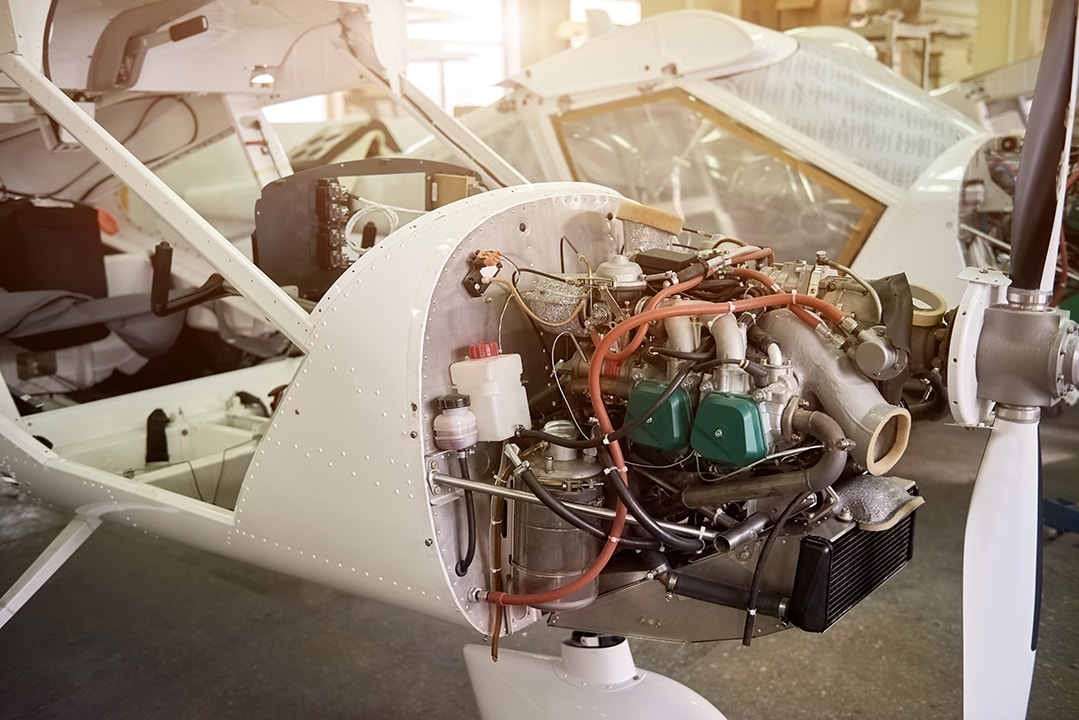
Powerplant and Propeller System
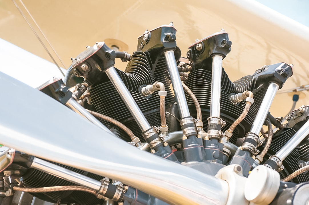
The standard engine in a C172S Skyhawk SP is the Lycoming IO-360-L2A: a fuel-injected, four-cylinder, horizontally opposed, air-cooled, normally aspirated powerplant producing 180 horsepower at 2,700 RPM. This engine drives a fixed-pitch, two-blade McCauley aluminum alloy propeller with a 76-inch diameter.
Because the propeller is fixed-pitch, RPM is controlled solely by the throttle there’s no propeller control lever in the cockpit. This simplifies operation for students learning engine management while still delivering reliable performance for training and cross-country operations.
Induction System
Air enters through a filtered inlet on the lower cowling, passes through an air filter, and flows to the fuel injection servo where it mixes with fuel. The alternate air door provides an emergency air source if the primary filter becomes blocked by ice or debris. Unlike carbureted engines, fuel-injected variants don’t require carburetor heat eliminating one potential source of pilot frustration and error.
Ignition System
Dual magnetos provide ignition redundancy, with two spark plugs per cylinder. Each magneto fires one set of plugs independently. During the runup, pilots check each magneto individually a drop of 125 RPM per magneto is acceptable, with a maximum differential of 50 RPM between the two. This redundancy means the engine continues running even if one magneto fails completely.
Carbureted vs. Injected Engine Differences
Older 172 models the 172N, 172P, and early 172R used the Cessna 172 carburetor with carbureted O-320 or O-360 engines. These variants require carburetor heat application in potential icing conditions and during power reductions. The fuel-injected IO-360 in the 172S eliminates carburetor icing risk but can be more susceptible to vapor lock in hot weather. Starting procedures also differ: carbureted engines use a primer, while injected engines prime via the electric fuel pump.
Cockpit Controls and Instrumentation
Pilots manage the engine through two primary controls: the black throttle and the red mixture lever. The throttle controls power output while the mixture adjusts the fuel-to-air ratio for altitude and economy. Typical leaning procedures involve pulling the mixture back during cruise flight until engine performance peaks, then enrichening slightly.
The G1000’s Engine Indication System displays digital RPM, fuel flow in gallons per hour, exhaust gas temperature, cylinder head temperature, oil temperature and pressure, and calculated percent power. These readings help pilots identify trends and catch problems before they become emergencies.
Fuel System
A typical C172S carries 56 gallons total fuel in two integral wing tanks 28 gallons per tank with 26.5 gallons usable in each, yielding 53 gallons usable capacity. Both tanks feed the engine simultaneously during normal operation, eliminating complex fuel management for students while ensuring balanced fuel load throughout the flight.
Fuel Flow Path
Fuel flows through the system in a predictable sequence:
-
Wing tanks (gravity-fed from the left side wing and right wing)
-
Fuel selector valve located under the cabin floor
-
Fuel strainer and sump assembly
-
Engine-driven fuel pump
-
Fuel injection servo
-
Fuel distribution manifold
-
Individual injectors at each cylinder
-
Fuel Tank Capacity and Venting System
The electric auxiliary fuel pump assists with priming before start and provides backup if the engine-driven pump fails. It’s also used during takeoff and landing as an extra safety measure.
Flight Control System
The C172 uses conventional primary flight controls: ailerons for roll, elevator for pitch, and rudder for yaw. All surfaces are manually operated through cables, pulleys, and bellcranks with no hydraulic boost. The control wheel operates ailerons and elevator simultaneously while rudder pedals control the rudder and provide nosewheel steering on the ground.
This direct mechanical linkage produces relatively heavy but predictable control forces that give students excellent feedback about the airplane’s state. There’s no disconnect between control input and aircraft response.
Primary Controls
Ailerons are constructed as part of the wing trailing edge, deflecting differentially to create roll. Typical deflection is 25 degrees up and 17 degrees down the differential helps minimize adverse yaw during turns. Elevator deflection controls pitch attitude and is especially critical during landing flare and stall recovery. The rudder coordinates turns and counteracts adverse yaw and propeller effects.
All cable tensions are periodically tested and adjusted during maintenance. Pilots can identify binding or unusual friction during preflight by moving controls through their full range and noting any unusual resistance.
Trim Systems
The elevator trim tab provides the primary pitch trim, controlled by a trim wheel on the center pedestal. Rotating the wheel forward provides nose down trim; aft rotation provides nose-up trim. A position indicator shows current trim setting. Some models include electric trim controlled by a switch on the control yoke, allowing hands-on adjustment during flight.
Aileron trim is ground adjustable only a small bendable tab on one aileron that maintenance technicians set to correct for rigging differences. Rudder trim on most models is also a fixed or ground-adjustable tab, though some installations include a cockpit-adjustable rudder trim knob.
Flap System
The C172S uses single-slotted, electrically actuated trailing-edge flaps with four detent positions: 0 degrees, 10 degrees, 20 degrees, and 30 degrees. A flap switch in the cockpit controls extension and retraction, with a position indicator showing current deflection on the instrument panel or G1000 display.
The flap motor draws significant electrical current and is protected by both a circuit breaker and limit switches that prevent over-travel. Full flap deployment increases lift and drag, allowing slower approach speeds the POH indicates approach speeds around 61 knots with full flaps for short-field operations.
Control Feel and Safety Features
The C172's mechanical control system keeps things simple there's no need for artificial feel systems or tricks to mimic the real thing. Control forces just get heavier as you go faster so you get a nice sense of what's going on. And if one of the cables snaps, you'll still be able to fly the plane to a safe landing although that's an extremely rare event.
Older 172 models had flaps that went down to 40 degrees, but later versions maxed out at just 30 degrees to make go-around jobs a bit easier. Some early birds even had manual flaps instead of the electric system we use now.
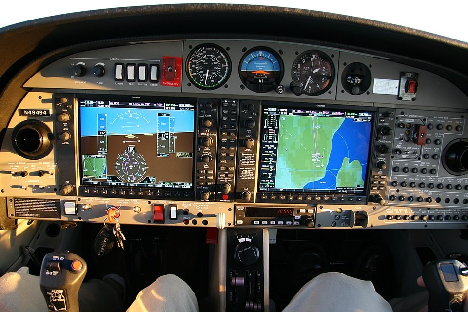
Avionics and Integrated Cockpit Systems
In a modern C172S Skyhawk SP with the G1000 or G1000 NXi glass cockpit, you'll be flying with a system that's transformed the way we do general aviation training. The heart of it is two 10-inch LCD screens one to show you what's going on with the plane and another to handle all the functions you need.
That setup replaces the old six-pack of round gauges and makes your life as a pilot a whole lot easier. And with the G1000, you'll be proficient in the avionics systems in use in big commercial transport category planes from day one.
Core Avionics Components
The G1000 system integrates multiple subsystems into a cohesive package:
-
Dual WAAS GPS receivers providing precision navigation and approach capability
-
Dual VHF NAV/COMM radios for navigation and communication
-
Mode S transponder with ADS-B Out and In capability (post-2020 fleets)
-
Audio panel for communication and audio switching
-
Integrated Engine Indication System displaying all powerplant parameters
The Attitude Heading Reference System replaces traditional gyroscopic instruments with solid-state sensors, eliminating vacuum system failures that plagued earlier models. An Air Data Computer processes pitot-static inputs to calculate airspeed, altitude, and vertical speed.
Power Distribution and Protection
Avionics buses (AVN BUS 1 and AVN BUS 2) handle power distribution, taking care of all the sensitive electronics on board. They each feed different components, so if one bus goes down, you still got power coming in from another. The main bus keeps the critical instruments up and running even if only part of the electrical system is working.
We've got a standby battery that's just for keeping the G1000 systems online even if the main power source fails. When you lose power, the standby battery will keep your PFD running for a good 30 minutes enough time to get the plane down safely.
Integrated Safety Features
Many G1000 NXi-equipped C172S aircraft include additional safety and automation features:
-
Autopilot (Garmin GFC 700 if installed) with altitude hold, heading hold, and navigation tracking
-
Flight director providing guidance bars for manual flying
-
Altitude preselect with alerting
-
Synthetic Vision Technology showing terrain representation on some NXi aircraft
-
Traffic alerting (TIS-B or TAS depending on equipment)
-
Terrain awareness and warning
-
Weather datalink via XM satellite
Electronic Stability Protection in newer G1000 NXi upgrades gently banks the aircraft to recover from excessive roll or pitch angles a valuable safety net during training when students may inadvertently approach unusual attitudes.
Cabin Electronics Integration
The C172S is really designed to be a flying classroom so we've got twin USB power ports so students & instructors can charge up their devices and run through all the latest electronic flight bag apps. We've also got audio jacks at all four seats so the whole crew can hear the radio and intercom.
LED interior lighting keeps the cabin nice and bright without burning a load of power or giving off too much heat a nice touch to round out the package and get you comfy while you're learning the ins & outs of modern instrument flying with the G1000 on board.